Interesting facts
Smoke removal systems
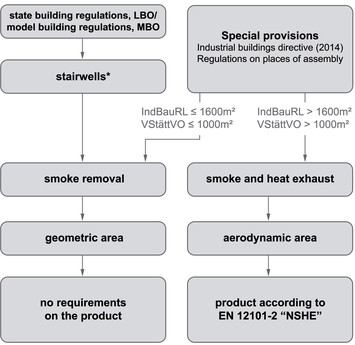
Smoke removal systems are openings that possess geometric smoke outlet areas (Ag). Building regulations do not pose any specific requirements on the manufacturing of a smoke removal product.
The general formula used to calculate the necessary area reads: Ag = a · b
The calculation may include all openings as long as it takes into consideration all obstacles, such as window reveals and window lintels, and factors in that area Ag must not be greater than the clear area of the window.
Smoke and heat extraction systems
Smoke and heat extraction systems are devices with smoke outlet areas (Ag) that possess an aerodynamic effect. The requirements posed on these natural smoke and heat extraction systems (NSHE) are spelled out in standard EN 12101-2. Among other things, these requirements call for wind tunnel measurements to determine the aerodynamic coefficient (Cv0), temperature and snow load tests as well as long-term tests to evaluate the system’s suitability for NSHE and ventilation purposes. An NSHE system is always composed of a unit that comprises a window with drive(s) and all necessary fitting parts.
The formula used to calculate the necessary area reads:
Aa = a · b · Cv0
The value Cv0 is given in the relevant test results and varies with the installation position and the opening angle of the window.
These is no general stipulation as to which conditions demand the use of smoke removal systems as opposed to a certified NSHE system. For the requirements that apply in your specific situation, refer to the relevant state building regulations (LBO) and the model building regulations (MBO) as well as to the applicable guidelines and regulations such as the Model Industrial Buildings Directive (MindBauRL) or the Regulations on Places of Assembly (VStättVO).
A geometric cross section is the sum of all opening surfaces. The calculation of these surfaces must take into account window reveals, window lintels, posts and bars as well as other obstacles (image 1). Another factor to be considered are the installation situations, e.g. simultaneously opening windows that are installed close to one another (image 2) or windows that open in close mproximity to a wall (image 3). When dealing with these types of situations, it is of particular importance to exclude the lateral triangles from the calculation or include them only to the necessary extent.
The State of North-Rhine Westphalia (Ministry for Construction, Living, Urban Development and Transport) and TÜV Rhineland have issued contradictory statements as to whether the lateral triangles may be included. Since not regulated by law, the calculations may include all additional surfaces.
Mode and state building regulations
by example of smoke removal in stairwells
Model building regulations
Excerpts from the model building regulations (MBO) Version November 2002 § 35 Required stairwells, exits (8) It must be possible to properly ventilate required stairwells and provide for smoke extraction as a means to support efficient firefighting operations. 2. be fitted with an opening at the topmost position that allows for appropriate smoke removal.
Openings intended for smoke removal […] must have a free cross section measuring at least 1 m² in every stairwell and be fitted with fixtures that are designed for opening its closures and can be operated from the ground floor and from the topmost landing.
State building regulations
Each federal state of Germany has defined their own building code (BauO) which, at times, contains stipulations that go beyond the requirements set forth in the model building regulations. Example North-Rhine Westphalia (NRW)
State building regulations (BauO NRW), § 37 Stairwells
(12) Buildings with more than five floors above the ground surface and required stairwells on the interior require that a smoke outlet be fitted with an opening at the topmost position of a required stairwell to provide for appropriate smoke extraction. The smoke outlet must possess a smoke outlet opening with a free cross section measuring at least 5 per cent of the footprint, but no less than 1 m². It must be possible to operate the smoke outlet from both the ground floor and the topmost landing. Exceptions may be permissible if the smoke can be discharged in a different way.
Federal state | interior stairwell | other stairwells | Area | Operation |
Baden-Württemberg | no requirements for non-auxiliary constructions | |||
Bavaria | yes | more than 13 m | at least 1 m² | Ground floor and topmost landing |
Berlin | yes | more than 13 m | at least 1 m² | Ground floor and topmost landing |
Brandenburg | yes | more than 13 m | at least 1 m² | Ground floor and topmost landing |
Bremen | yes | more than 5 floors | at least 5% of the footprint, at least 1 m² | Ground floor and topmost landing |
Hamburg | yes | more than 13 m | at least 1 m² | Ground floor and topmost landing |
Hesse | yes | Buidling class 5 | at least 1 m² | Ground floor and topmost landing |
Mecklenburg-West Pomerania | yes | more than 13 m | at least 1 m² | Ground floor and topmost landing |
Lower Saxony | – | – | – | – |
North-Rhine Westphalia | yes | more than 5 floors | at least 5% of the footprint, at least 1 m² | Ground floor and topmost landing |
Rhineland-Palatinate | yes | more than 5 floors | at least 5% of the footprint, at least 1 m² | Ground floor and topmost landing |
Saarland | yes | more than 13 m | at least 1 m² | Ground floor and topmost landing |
Saxony | yes | more than 13 m | at least 1 m² | Ground floor and topmost landing |
Saxony-Anhalt | yes | more than 13 m | at least 1 m² | Ground floor and topmost landing |
Schleswig-Holstein | yes | more than 13 m | at least 1 m² | Ground floor and topmost landing |
Thuringia | yes | more than 13 m | at least 1 m² | Ground floor and topmost landing |
(1) Stairwells with a footprint in excess of 40 m² require special provisions.
(2) Requirements may mandate that the smoke outlet be operable from the other side as well.
Example of how to implement a smoke removal system in a stairwell that is operated by an electric motor.
OG upper Floor
EG ground Floor
UG basement Floor
Smoke dissipation via electrically operated skylight
The supply air can be fed electrically as well.
Central SHE unit as power supply and control unit
Manual activation by pressing the fi re pushbutton (manual fire alarm)
Automatic activation via smoke detector (automatic fire alarm)
The recommended option for daily ventilation is operation by ventilation pushbutton.
We off er the following product solutions for preventing damage arising from excess wind speeds and rain: Rain sensor, wind and rain sensor (combined)
It is imperative for the planning of an electric smoke and heat exhaust system to define the corresponding fire groups, ventilation groups and motor groups. These definitions can then be used to prepare a wiring overview including specifications for cable types and cable cross sections.
In addition, the wiring diagram will specify the assignment of the fire pushbuttons (manual activation), the smoke detectors (automatic activation), the ventilation pushbuttons and the wind / rain sensors to the motor groups. The mapping of these components is accomplished by identifying the motor group number on the controls and activation elements.
As shown in the sample building and wiring diagram, there need to be 3 fire groups (one for each section of the building) and 5 ventilation groups spread across 5 motor groups. The wiring diagram also indicates that the stairwell will be equipped with 2 fire pushbuttons and 2 ventilation pushbuttons and specifies how the components need to be wired.
The wind and rain sensor acts on all motor groups, which is why it is labelled 1-5. This presentation principle can be applied to every building and to stairwells.
1. see cable cross section diagram; cable with functional endurance according to Model Conduit Systems Directive
2. 6 x 0.8 mm²; cable with functional endurance according to Model Conduit Systems Directive
3. 4 x 0.8 mm², required are 2 wires; cable with functional endurance according to Model Conduit Systems Directive
4. 4 x 0.8 mm²; cable without functional endurance
5. 4 x 0.8 mm² up to 100 m; cable without functional endurance
6. 3 x ... mm²; cross section according to power consumption; cable without functional endurance
Note: This wiring sample is no substitute for individual planning.